Professional
drill chuck

Self-tighten Chuck System
Suitable for CNC machine tools and machining centers, suitable for high precision close cutting equipment, productive drilling coordinate boring machine and milling machine.
MORE
High Torque Drill Chuck
It's suitable for household, professional use of AC&DC and pneumatic tools.It's easy to tighten, so that the output torque can become larger, It can also be customized according to customer requirements.
MORE
Key Type Chuck
The wrench series drill chuck is divided into light and heavy types. Our company has a complete range of light and heavy types, with high precision and clamping force, suitable for electric tools, various desktop tools, and various lathes.
MORE
10MM Keyless Chuck
It's suitable for household, professional use of AC&DC and pneumatic tools.It's easy to tighten, so that the output torque can become larger, It can also be customized according to customer requirements.
MORE
13MM Keyless Chuck
It's suitable for household, professional use of AC&DC and pneumatic tools.It's easy to tighten, so that the output torque can become larger, It can also be customized according to customer requirements.
MORE
Keyless Chuck With Lock System
We have a variety of patented structures for keyless chuck with lock,which can be used in all kinds of AC or 18V, 20V DC brushless impact drill and can meet the use of different grades of tools.
MORE
Machine Accessories
It's suitable for CNC machine tools, medium speed light load, medium speed heavy load, high speed light load and other conditions, and also has a waterproof and dustproof design.
MORE
chuck
Self-Contained Jaw Dressing Device Power Chuck
Equipped with a self - repairing jaw device, ultra - precision power chuck
MORE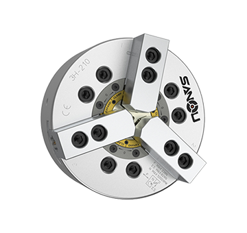
5μm Large Though Hole Super Precision High Durable Power Chuck
MORE
Pull Lock Power Chuck
High radial gripping force and high accuracy. Suitable for heavy maching.
MORE
Pull Lock Power Chuck
Radial clamp and axial pull down at the same time, keep the workpiece attaching close to the base surface of the chuck.
The body and the cylinder pull-down mechanism are heat-treated
and fine boring, which guarantee the clamping precision and durableness.
MORE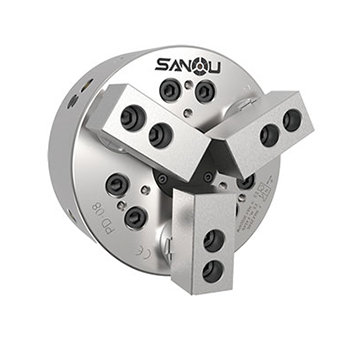
HYDRAULIC CYLINDERS
For short form,light weight and high speed rotary cylinder.Built-in safety check valves and pressure relief valves.
MORE
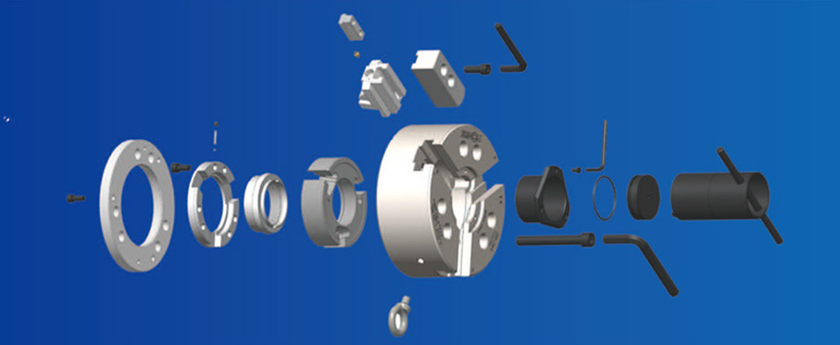
Micro μm-level Ultra Precision Power Chuck
A new generation hydraulic chuck with ultra-high accuracy and excellent continuous performance
Unprecedented precision, the pinnacle of the new generation of dynamic cards
MORE
Manual Chuck
Our company produces a complete range of chucks with outstanding quality.We can produce two jaws, three jaws, four jaws, six jaws and other series of single action and self-centering chucks.
MORE
PLUS-M High-precision Adjustable Chuck
1.Specific adjustable structure, adjustable precision ≤0.005 mm.
2. All components undergo grinding processes, resulting in higher product stability and smoother, more flexible rotation.
3. The disc body is made of high-quality QT500 ductile iron, offering high durability and a long service life.
4. Application scenarios: Suitable for grinders, high-precision CNC lathes, and various other high-precision machining equipment.
MORE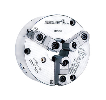
PLUS High-Precision Chuck
High Accuracy: Concentricity ≤ 0.02 mm, repeatability ≤ 0.01 mm for precise and stable machining;
Precision-Ground Parts: Ensures excellent stability and smooth rotation;
Durable Build: QT500 ductile iron body for long service life.
Applications: Suitable for grinding machines, high-precision CNC lathes, and other precision machining equipment.
MORE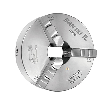
Harvest-High Precision Chuck
1. Forged steel disc body, high strength, high load, and high speed.
2. The claw and disc wire are made of 20 chromium manganese (20CrMnTi) alloy steel, which is impact resistant, more wear-resistant, and has a long service life.
3. Full process machining center production, German and Swiss testing equipment, ensuring batch product accuracy ≤ 0.03mm.
MORE
SAN OU Pro High Precision Chuck
SAN OU Pro high-precision chuck is the latest strategic product launched by Sanou
SAN OU Pro accuracy ≤ 0.03mm (radial, end face, outer circle)
MORE
News
updates
OEM&EDM
Services
About
san ou


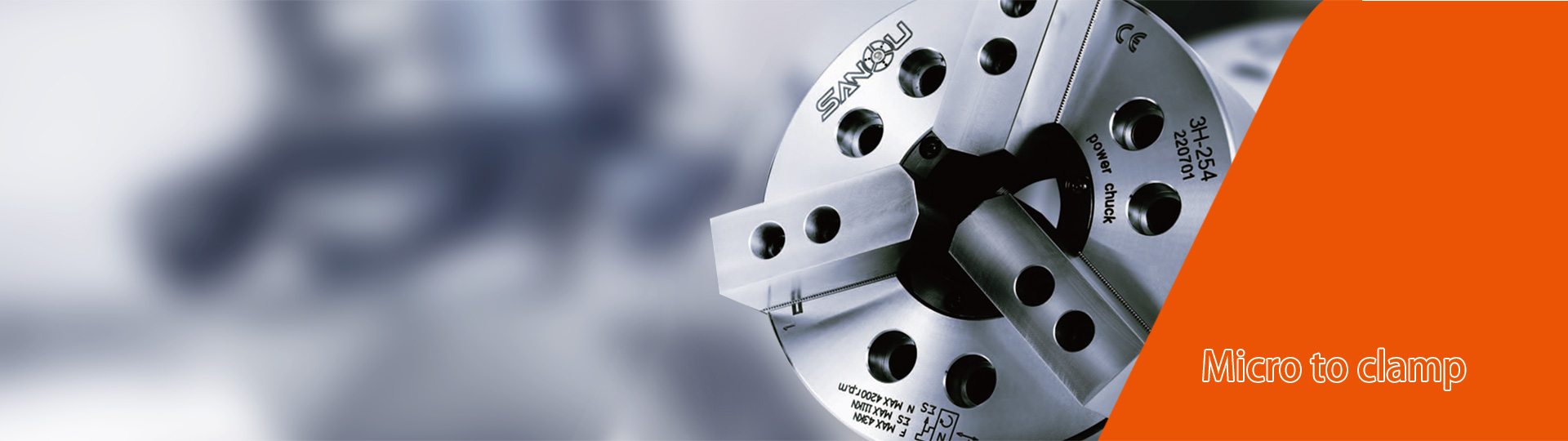
Who is Micro?
An ultra high precision and excellent continuous performance
New generation hydraulic chuck
Unprecedented precision, the pinnacle of the new generation of dynamic cards
Applicable machinery :
Various types of high-end CNC machine tools
Applicable scenario :
Clamping processing of metal bars, pipes, flanges, and disc profiles
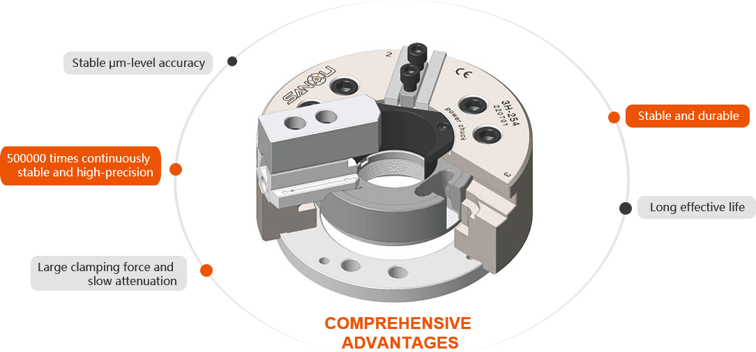
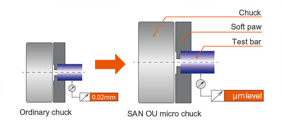
Disruptive μm-level accuracy
The new Micro for precision creates the hydraulic pressure that subverts cognition Chuckaccuracy:
after the jaw is formed, the repeated clamping accuracy is stable at u Level m, which is thetop of high-end manufacturing precision in the world
SAN OU Micro μm-level ultra precision motion card
Promote the clamping accuracy of China to the micrometer level
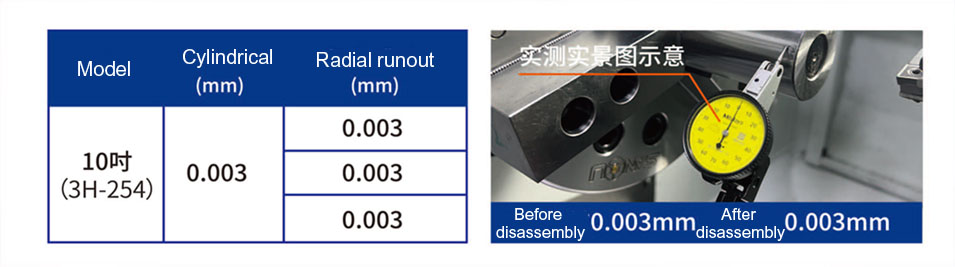
* The actual measurement accuracy of specific models can reach up to 3μm
How to ensure μm accuracy
A groundbreaking major upgrade
Laser quenching of key components, one-time clamping and forming
First to use CrNiMo alloy steel
Four times heat treatment process for disc body
Imported heat treatment equipment from Europe

Full closed loop digital factory
Full traceability of one item and one code
MES dynamic quality control
Constant temperature customized grinding
Intelligent tolerance selection
Online probe detection
Parameter Table

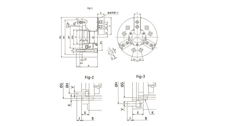
DIMENSION DRAWING
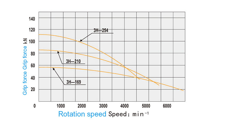
CLAMPING FORCE PERFORMANCE CURVE
DIMENSION TABLE
| Model size | A | B | C | D | E | F | G | H | J | K | L | M | N max. |
O max. |
O min. |
P max. |
P min. |
Q | S | T | U max. |
V | W | X | Y | Reference image |
| 3H-169A4 | 169 | 96 | 140 | 20 | 20 | 63.513 | 104.8 | 82.6 | 16 | 6-M10 | 45 | 5 | 32 | 22.75 | 9.25 | 31 | 19 | 2 | 19 | 31 | M55x2 | 6-M10 | 60 | 37 | 73 | Fig-2 |
| 3H-169A5 | 169 | 91 | 140 | 20 | 15 | 82.563 | 116 | 104.8 | 16 | 6-M10 | 45 | 5 | 32 | 22.75 | 9.25 | 26 | 14 | 2 | 19 | 31 | M55x2 | 3-M6 | 60 | 37 | 73 | Fig-1 |
| 3H-169A6 | 169 | 111 | 140 | 20 | 35 | 106.385 | 104.8 | 1333.4 | 16 | 6-M10 | 45 | 5 | 32 | 22.75 | 9.25 | 46 | 34 | 2 | 19 | 31 | M55x2 | 6-M12 | 60 | 37 | 73 | Fig-3 |
| 3H-210A5 | 210 | 109 | 170 | 25 | 23 | 82.563 | 133.4 | 104.8 | 14 | 6-M12 | 52 | 5 | 39 | 29.75 | 11.75 | 37.5 | 21.5 | 2 | 20.5 | 35 | M60x2 | 6-M10 | 66 | 39 | 95 | Fig-2 |
| 3H-210A6 | 210 | 103 | 170 | 25 | 17 | 106.385 | 150 | 133.4 | 18 | 6-M12 | 52 | 5 | 39 | 29.75 | 11.75 | 31.5 | 15.5 | 2 | 20.5 | 35 | M60x2 | 3-M6 | 66 | 39 | 95 | Fig-1 |
| 3H-210A8 | 210 | 126 | 170 | 25 | 40 | 139.719 | 133.4 | 171.4 | 24 | 6-M12 | 52 | 5 | 39 | 29.75 | 11.75 | 54.5 | 38.5 | 2 | 20.5 | 35 | M60x2 | 6-M16 | 66 | 39 | 95 | Fig-3 |
| 3H-254A6 | 254 | 120 | 220 | 30 | 25 | 106.375 | 171.4 | 133.4 | 18 | 6-M16 | 75 | 5 | 51 | 33.75 | 14.25 | 33.5 | 14.5 | 2 | 25 | 40 | M85x2 | 6-M12 | 94 | 43 | 110 | Fig-2 |
| 3H-254A8 | 254 | 113 | 220 | 30 | 18 | 139.719 | 190 | 171.4 | 24 | 6-M16 | 75 | 5 | 51 | 33.75 | 14.25 | 26.5 | 7.5 | 2 | 25 | 40 | M85x2 | 3-M8 | 94 | 43 | 110 | Fig-1 |
| 3H-254A11 | 254 | 145 | 220 | 30 | 50 | 196.869 | 171.4 | 235 | 28 | 6-M16 | 75 | 5 | 51 | 33.75 | 14.25 | 58.5 | 39.5 | 2 | 25 | 40 | M85x2 | 6-M20 | 94 | 43 | 110 | Fig-3 |
SPECIFICATION SHEET
| Model size | Through-hole diameter (mm) |
Rod stroke (mm) |
Claw stroke diameter (mm) |
Maximum allowable tensile force (KN) |
Maximum speed (r.p.m) |
Weight (kg) |
Moment of inertia (kg.m³) |
Outer diameter clamping range (mm) |
| 3H-169A4 | 45 | 5.5 | 22 | 57 | 6000 | 15.5 | 0.065 | 15-169 |
| 3H-169A5 | 45 | 5.5 | 22 | 57 | 6000 | 14.7 | 0.062 | 15-169 |
| 3H-169A6 | 45 | 5.5 | 22 | 57 | 6000 | 17.3 | 0.073 | 15-169 |
| 3H-210A5 | 52 | 7.4 | 33 | 82 | 5000 | 25.8 | 0.19 | 20-210 |
| 3H-210A6 | 52 | 7.4 | 33 | 82 | 5000 | 25 | 0.184 | 20-210 |
| 3H-210A8 | 52 | 7.4 | 33 | 82 | 5000 | 29.3 | 0.217 | 20-210 |
| 3H-254A6 | 75 | 8.8 | 43 | 111 | 4200 | 41 | 0.37 | 25-254 |
| 3H-254A8 | 75 | 88 | 43 | 111 | 4200 | 38 | 0.34 | 25-254 |
| 3H-254A11 | 75 | 8.8 | 43 | 111 | 4200 | 48.4 | 0.436 | 25-254 |

Follow Sanou Official Account

Follow Sanou Video Account

Pay attention to Sanou Tiktok
Copyright © 2023 SAN OU MACHINERY LIMITED COMPANY All Rights Reserved
Design & Production : Feisu.cn


